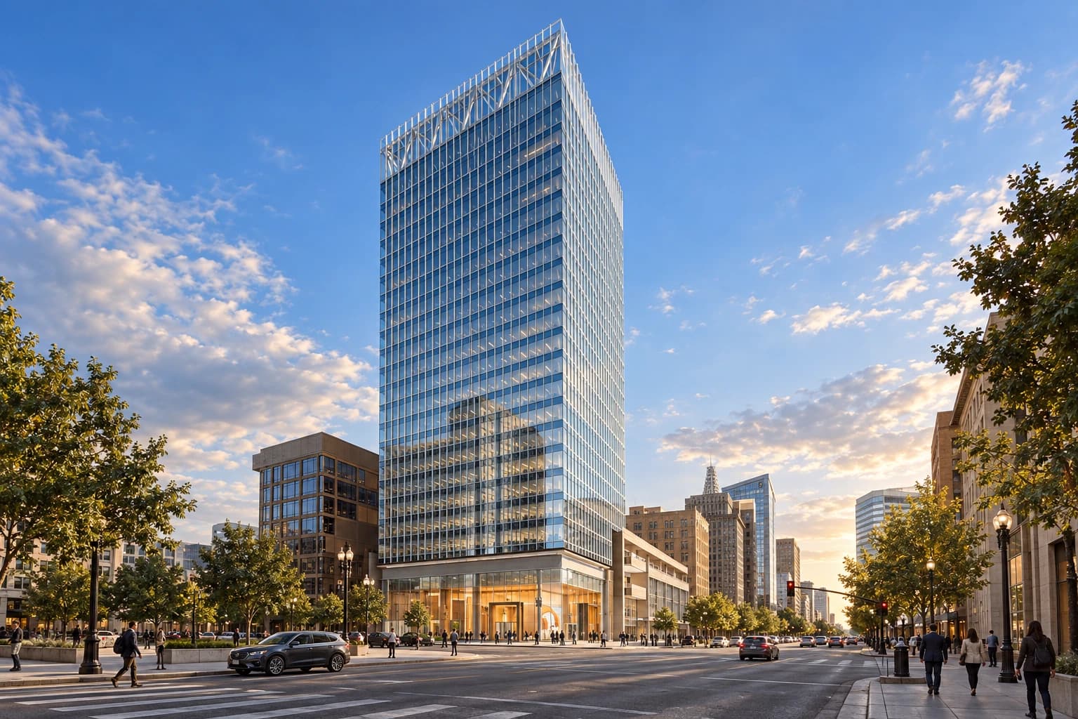
Office Tower
111 Main — Structural BIM for a Suspended Office Tower
Salt Lake City, Utah·2016·Skidmore, Owings & Merrill (SOM)
Structural BIM, technical documentation, and construction sequencing for SOM’s 111 Main tower in Salt Lake City.
Structural BIM · BIM Coordination · Technical Documentation
- Role
- Structural BIM Technician
- Firm
- Skidmore, Owings & Merrill (SOM)
- Client
- City Creek Reserve, Inc.
- Location
- Salt Lake City, Utah
- Year
- 2016
- Type
- Office Tower
- Status
- Built Work
- Tools
- Revit
In Brief
A tower supported from above to preserve the theater below.
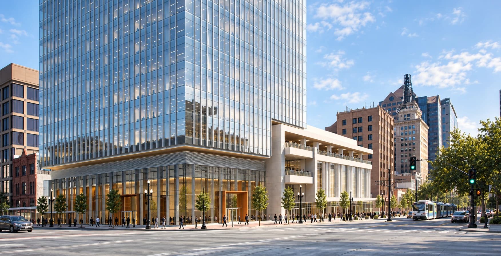
111 Main is a 25-story office tower in downtown Salt Lake City whose southern portion extends over the Eccles Theater. A roof-level steel hat truss suspends perimeter columns, allowing the office floors to span above the theater volume.
I was the main structural BIM technician for the project, working closely with Peter Lee to develop the Revit model, technical drawings, and documentation sequencing for this unusual structural system.
The Structural Problem
The theater occupies part of the tower’s lower southern footprint. Continuing a conventional line of perimeter columns down through that space would conflict with the theater below. The solution moved the support upward.
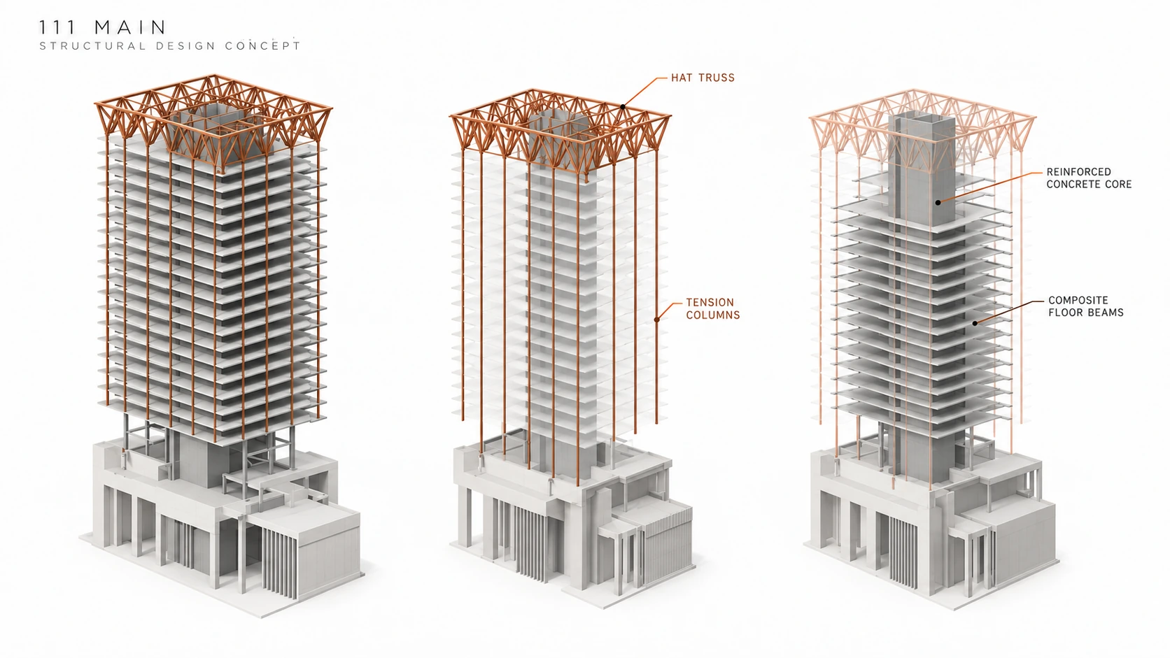
A reinforced-concrete core supports a roof-level, two-way steel hat truss. The truss carries 18 suspended perimeter columns, while long-span composite steel floor framing connects the core to the perimeter. This arrangement keeps the theater volume clear beneath the overlapping office floors.
The distinction matters: the hat truss cantilevers from the core; the perimeter columns hang from the truss. Describing the tower as suspended makes that support relationship clearer than describing the office floors as a simple cantilever. SOM’s structural overview explains the system in more detail.
My Role
Structural BIM Technician
- Served as the main BIM technician for the structural team
- Developed and maintained the structural Revit model
- Worked closely with Peter Lee on structural geometry and technical development
- Modeled the tower’s suspended structural relationship over the Eccles Theater
- Produced and coordinated technical structural drawings from the BIM model
- Sequenced construction logic through the project documentation
The following reconstructions explain the structural relationships behind my modeling and documentation work. They are explanatory views, rather than records of the original Revit model or the construction sequence.
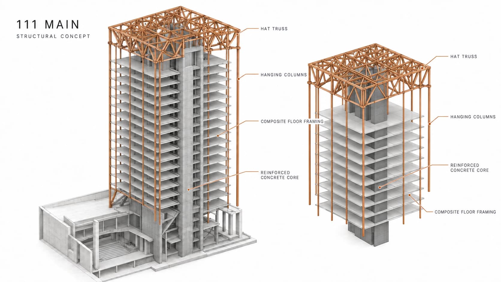
View the technical illustration at full size
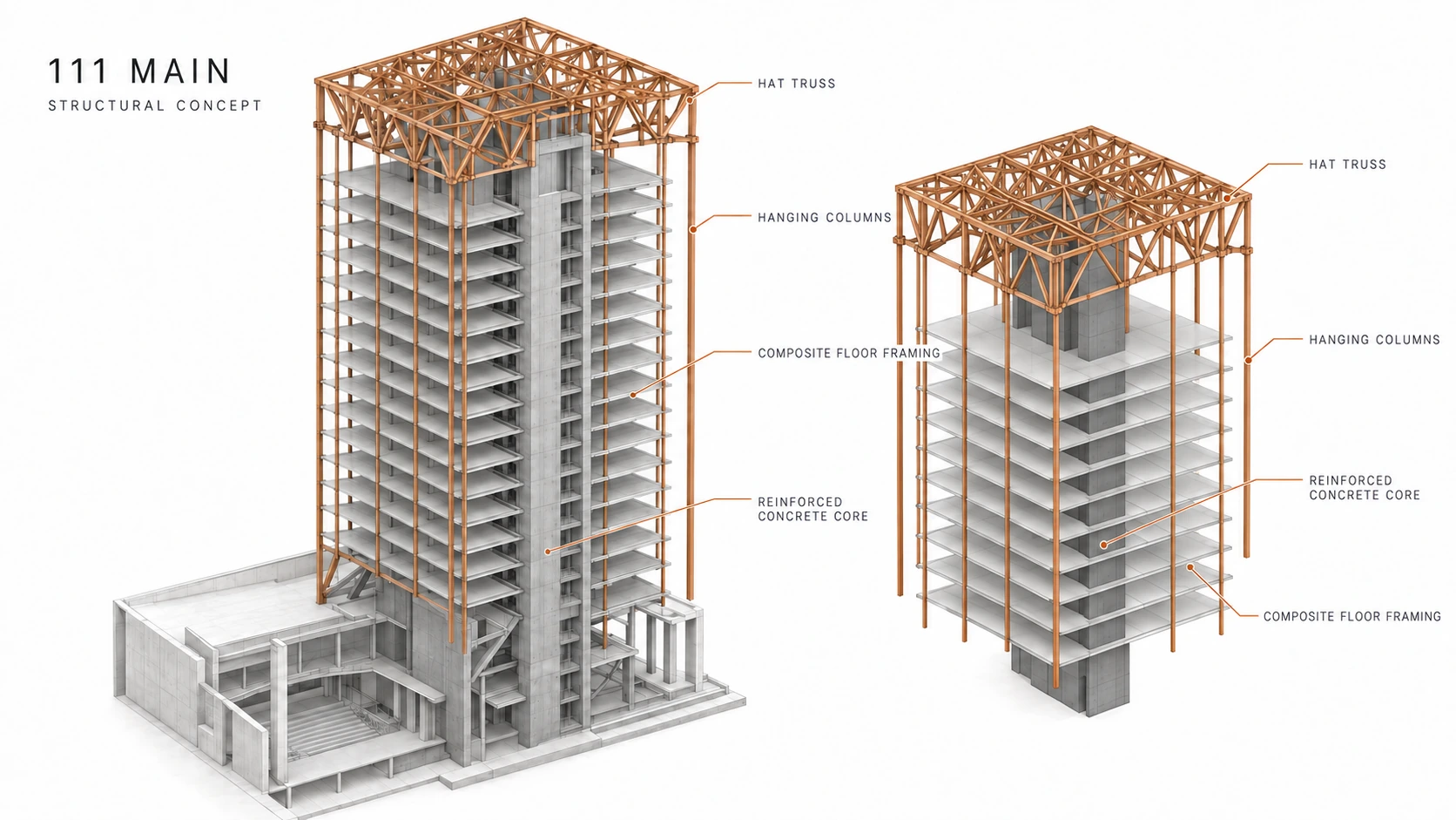
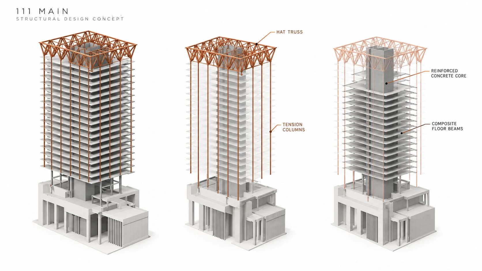
View the structural concept diagram at full size
Modeling the Structural Concept
The modeling task extended beyond repeating a typical floor. The concrete core, roof hat truss, suspended columns, and long-span framing had to read as a connected system, with the theater relationship visible in the structural geometry.
I developed the Revit model alongside the technical drawings so that plans, sections, and elevations communicated consistent structural information. The model provided a way to describe the unusual support relationships and carry them into coordinated documentation.
Documentation and Sequencing
My work also included sequencing the construction logic through the project documentation. The permanent support system depended on the roof-level hat truss, so the final geometry alone did not explain the construction sequence.
The documentation needed to distinguish the completed structural arrangement from the changing support conditions during assembly. My contribution was to model and communicate that logic in the technical documentation, working closely with Peter Lee as the project developed.
From structural concept to coordinated documentation
- 01
Understand the system
Establish the relationship between the concrete core, roof hat truss, suspended columns, and theater.
- 02
Develop the Revit model
Represent the structural geometry and its support relationships.
- 03
Coordinate drawings and sequence
Communicate geometry and construction logic through the technical drawing set.
- 04
Maintain coordinated documentation
Carry model development into consistent structural information.
What this project demonstrates
- Translating an unconventional structural concept into coordinated BIM documentation
- Modeling suspended framing and non-standard support relationships
- Using Revit to communicate structural geometry across technical drawings
- Connecting model development with construction sequencing and documentation
Project Attribution
Architecture and structural engineering: Skidmore, Owings & Merrill (SOM), with project collaborators credited in SOM’s project record. My contribution presented here is structural BIM modeling, technical documentation, and documentation sequencing.
All four images are newly created portfolio visualizations or technical reconstructions supplied for this case study. They are not original project photography, historical Revit screenshots, or archival construction drawings. The diagrams explain the structural concept and should not be read as exact member layouts or erection instructions.